|
Search: |
|
Search: |
HOME → ARTICLES → ARTICLE: Proper Mold Design for Permanent Mold Production

President
CMH Manufacturing Company
www.cmhmfg.com
The demand for permanent mold castings has steadily increased with automotive parts leading the way: suspension links, intake manifolds, pistons, and other functional parts of internal-combustion engines are typical applications. Other applications include aviation engines, missiles, motor housings, nozzles, fan cases, outdoor lighting standards, lawn mower chassis, barbeque grills, and kitchen pots and pans.
The decision to use tilt pour permanent molding should be based on thorough engineering and production cost studies. Properly made tilt pour castings have the following advantages:
When designing molds for permanent molds casting, the most common mistake foundry engineers make is not understanding the tilt pour process or understanding the individual foundry’s requirements.
In permanent mold casting, solidification occurs much more rapidly than in sand casting. However tilt pouring allows better filling of the mold with minimum turbulence and controlled thermal gradients to establish directional solidification towards a riser. The rigidity of a permanent mold necessitates some differences in the application of these principles. It is essential that the entire casting and its gating system be removed with a simple parting from the mold. Removal must be possible without excessive mechanical force on the casting or without excessive abrasion of the mold coating. A front ejector will ensure that the casting draws straight and pulls with the movable mold half. Heavy sections are generally placed on the parting line to permit feeding. Sprues, runners, gates and risers are also placed on the parting line so they can be stripped with the casting. The casting and gating system must be arranged to promote directional solidification starting in the remote areas and progressing towards the riser.
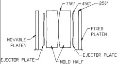
Due to the wide variation in cross sectional area of commercial castings it may be necessary to use highly conductive chills, air cool, water cool or take advantage of varying the mold wall thickness in order to promote directional solidification. Adequate gravity head should be provided to ensure filling of all parts of the cavity. Ample flat area should be allowed to seal against metal leakage at the parting line. Two inches at the bottom and one and one half inches at the sides is normally enough to seal molds up to thirty inches square. Caution must be used when designing molds not to make them too rigid. The parting line is the hottest portion of a mold, and each face of the mold/platen assembly will run progressively cooler (see fig. 1). Different heating of the mold will cause the mold to open at the parting line. In order to prevent mold warping at the parting line, over all mold thickness should be held to a minimum and stiffening ribs should not be used.
Mold design can dramatically affect casting quality as well. When design-ing a mold, the following factors must be considered.
Venting – All the air in the mold must escape as the mold is filling. Natural outlets, such as the parting line, and clearances around ejector pins, usually provide adequate venting. A properly designed gating system in the tilt pour process can reduce the venting necessity. The molten metal can be taken to the bottom of the mold, thereby forcing the air out the top as the mold is tilted. In some cases, supplemental venting must be added.
Commonly used venting methods include:
Gating/risering – As the mold is tilted, molten aluminum enters the permanent mold and loses heat rapidly compared to sand molds. The rapid cooling also necessitates rapid filling. In general, the gating/risering system in the tilt pour process should accomplish the following:
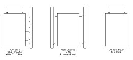
Figure two illustrates three types of tilt pour gating. The multi ingate system has lower finishing cost, but can cause turbulence and dross defects. If high quality levels are required, the continuous ingate might be desirable. This system could be used with a top riser and/or shrink bobs as necessary.
Direct gating can be used very effectively in tilt pouring because the automatic tilting of the mold eliminates human variability in the pour rate. Additionally, as the liquid aluminum enters the mold it flows through a static skin of aluminum oxide. The oxide acts as a barrier allowing only clean metal to enter the mold cavity.
The use of a side riser permits more control over distribution of the metal into the casting cavity through the gates. With castings of irregular cross section, it may be desirable to vary the rate of fill to sections of greater or less mass. A programmable tilt option was designed to allow the caster to very the tilt rate, therefore the mold fill rate, as necessary. In such cases multi ingates may be placed at various levels to allow metal to flow at the most desirable rate. For large castings, the gating system might be placed on both sides. In applications when a runner/riser is being used, a runner extension should be used to prevent the backwashing of dross contam-inated first metal of the pour.
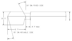
The actual dimensions of the mold and gating system will depend on the weight and dimensions of the casting to be produced. Figure four is given as a guideline. All the dimensions are based on the thickness of the casting which is referred to as “T”. In permanent mold casting riser sizing is critical. The riser must be large enough to eliminate shrinkage defects. In some cases an oversize riser van superheat the mold and actually cause a shrinkage defect in the casting. Furthermore, a riser in which metal freezes too slowly may delay the opening of the mold until excessive contraction stresses have developed in the casting. An over-size riser will increase cycle time and reduce production.
Chills – In absence of other variables, the thin sections (sections of low modulas) will naturally solidify before the heavy sections (sections of higher modulas). When the shape permits, it is preferred to place the casting in the mold so that solidification starts in the thinner sections and progresses to the heavier sections. Due to the wide variation in castings, this is not always possible and a hot spot will form. Some relief may be obtained by adding ribs to a boss to introduce more feed metal into the heavy section. Ribbing is not always effective or the casting may not be modifiable. In such cases, it is prudent to cool the heavy section of the mold so that the casting will solidify quickly.
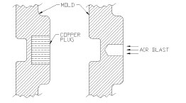
Localized chilling can be obtained by installing copper inserts (fig. 4). Extending them outside the mold and cutting cooling fins into the chill can increase their effects. Air chills are holes drilled into the mold and a blast of air is blown into to the relief. Moderate control of solidifications can be accomplished by varying the thickness of the mold coating.
The importance of properly designed permanent molds cannot be over looked. Mold design and mold quality directly effect scrap rate, casting quality, and foundry profitability.
Privacy Policy and Terms and Conditions.
Copyright © CMH Manufacturing Gravity Die Casting Machines. Web published by Marketing Options, LLC